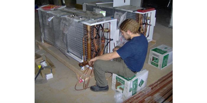
 This article on maintenance in refrigeration systems complements the first part of the note published in the previous edition called "Most common errors in refrigeration". by Giovanni Barletta*
The maintenance of commercial refrigeration systems is exposed to the stereotype of all maintenance programs, in different areas of the industry in general and is very well defined by these famous phrases: "When everything is going well nobody remembers that it exists,
When it goes wrong they say it doesn't exist,
When it is to spend it is said that it is not necessary,
But when it doesn't really exist...everyone agrees that it should exist..."
.A. Suter - Westinghouse."
Maintenance is always seen as an expense and not as an investment, it does not have adequate resources and is not in the priorities of senior management, and what is even more regrettable, is that its impact on operating costs is not measured when it is not done in the appropriate way, either due to loss or loss of product, energy inefficiency in the refrigeration cycle, which implies cost overruns in the energy bill, premature aging of equipment, high costs due to frequency in replacement of parts, labor cost overruns in addition to the impact on the production chain or on the image of the retail business, when the buyer does not find the products kept within an adequate cold chain.
Maintenance, more than a prevention of the causes mentioned above, which in itself returns the investment in a very short time, has to be understood as a tool to prevent a failure, and also allows analyzing parameters aimed at the efficient management of energy.
1. The first thing that a service provider must do and - it is what is almost never done - is to know in depth the system that is going to intervene, since as we showed in the previous article, there are different architectures, different criteria in control and automation systems, as well as details as simple as knowing the defrosting parameters, drip times, valve and regulator adjustments; it would be endless to enunciate the parameters that make each system characteristic and particular.
2. Having appropriate instruments and tools, without these is very difficult to get to the detail, either of a diagnosis, or the fulfillment of a routine that actually adds value to the service. Within this requirement it must also be understood that they are properly calibrated, thus avoiding that later they are not objects of doubt or require double verification because they are inconsistent.
3. Make a list of basic readings, and it is understood that they must be taken at the key points of the system, some of them and minimum would be:
- Compressor Discharge Temperature
- Temperature & Pressure at the Outlet of the Condenser
- Temperature & Pressure at the Evaporator Outlet
- Ambient Temperature (Ext. & Int.)
- Compressor Suction Temperature
- Supply voltage to the Compressor per phase
- Power Consumption in Amperes per phase
- Compressor Discharge Pressure
- Compressor Suction Pressure
4. Perform basic calculations
- Overheating at the evaporator outlet
- Total overheating (in compressor suction)
- Discharge gas temperature
- Subcooling of liquid at the outlet of the condenser and before the expansion valve
- Temperature difference between air and refrigerant in the condenser
- Temperature difference between air and refrigerant in the evaporator
- Calculate voltage and current imbalances using averages and deviation as shown in the example in Figure 1
- Compare all these values against the original design conditions or against the values in the commissioning of the system
- Keep a historical record of all this data, it will always be useful to you
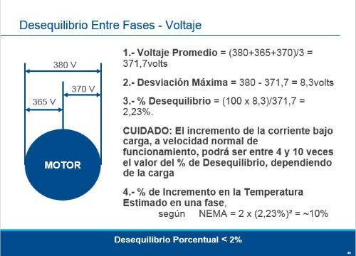
Figure 1. Example of voltage imbalance calculation.
Routines required to avoid premature failures
1. Prevent overheating of the refrigerant in the discharge and with it of the compressor avoiding exceeding the maximum temperatures that would generate premature lubrication failures and generation of contaminants to the system, for this:
- Verify that the compressor selection is based on the specific application (in your operating range) and with your recommended cooling system
- Control the refrigerant gas load
- Clean the condenser and check the operation of the fans
- Verify the operation of the liquid injection system
- Properly isolate the suction line
- Correct adjustment of the overheating of the expansion element
- Review the adjustment of the high and low pressure switch
- In graph 2 are the recommended discharge temperature values as well as the maximum permissible.
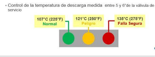
Figure 2. Recommended discharge temperature values
2. Guarantee the adequate return of oil to the compressor and avoid lubrication failures due to its absence, for which it is essential:
- Verify that pipe diameters are properly selected
- Avoid possible obstruction in the hole of the suction accumulator
- Check the direction of rotation of the Scroll compressor
- Check slopes in the suction line to the compressor (1" every 20', approximately)
- Arrange traps in ascending suction sections of more than 1.50 meters
- Install oil separator when the condition requires it
- Search for and repair potential leaks
- Correctly adjust pressure and temperature controls to prevent compressor operation in short cycles
3. Prevent liquid from returning to the compressor, either in operation or in a prolonged shutdown and for this:
- Properly select the unit, evaporator and expansion valve
- Avoid keeping cold room doors open for too long
- Review and correctly apply the full pumping cycle (Pump Down)
- Review and schedule thaws properly
- Apply Suction Accumulator
4. Avoid flooded starts that can cause a blow of liquid and for this:
- Do not exceed the refrigerant gas load
- Install suction accumulator when required by application
- Apply or revise complete pumping system
- Review and schedule thaws properly
- Check the operation of the crankcase heater
- Keep the crankcase heater on during gas charging and before commissioning
- Avoid long periods of shutdown and when this occurs, heat the oil for at least 12 hours
5. Keep the system always within the highest degree of cleanliness thus avoiding the formation of acids and with it the corrosion of the internal components of the system. The appearance of a system with this problem is very easy to identify after failure, as shown in Figure 3.
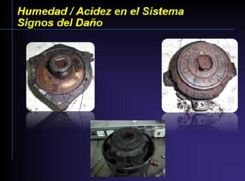
Figure 3. System with evidence of humidity and acidity
Always use high vacuum pumps that guarantee that it can reach 500 microns, do not leave this in the hands of a set of pressure gauges. Notice in Figure 4 the important differences between the inches of mercury in the pressure gauges and a true vacuum in microns.
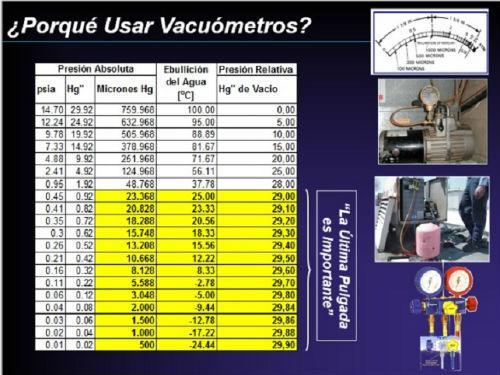
Figure 4. Comparative micron scale 6. Important observations in any maintenance routine
Bubbles in the peephole or liquid visor, which may mean:
- Low refrigerant gas load or insufficient subcooling of the liquid at the outlet of the condenser
- Low condensation pressures
- Restrictions on the liquid line or filter dryer
Temperature differences in the filter dryer before and after it or finding it snowy from it implies pressure drops due to obstruction and must be replaced.
Observe the oil peephole of the compressors when it starts. It should not be foamy or a milky color, it implies the presence of diluted liquid in the carter.
Observe in detail the levels of the liquid bottle (or liquid receiver), understand that this level depends on the demand for refrigerant in the evaporators, the number of them that is thawing, among other variables, but unjustified decrease almost always implies leaks and forces a very exhaustive search for it.
* Giovanni Barletta is the Technical Manager of Emerson's Andean, Caribbean and Central Americas Area, and current president of the Colombian Association of Air Conditioning and Refrigeration (ACAIRE). You can be contacted at the electronic broker: [email protected]


