Everything you need to know about the pressure-independent control valve.
By Fratelli Pettinaroli
A PICV, Pressure Independent Control Valve, is a valve that can be installed in chilled water heating and cooling systems to provide the following:
• Flow control: allows control of the modulation of heating/cooling outputs
• Flow regulation – allows flow rates to be set to specified design values
• Differential Pressure Control: Ensures constant differential pressure through the control valves, regardless of changes in pump speed or valve shut-off elsewhere in the system.
This means that each PICV performs the function of up to three different valves that would otherwise be necessary for the proper operation of a facility. These 3 valves would be the throttle valve, the two-way control valve, plus a differential pressure control valve.
PICVs are the best solution for flow control through air handling units, fan coil units, and chilled beams fed from variable flow heating and cooling systems. These are systems in which the pump speed and, in turn, the flow rate, vary in response to heating or cooling demand, resulting in savings in pump energy.
It is now very important to define with the utmost clarity how a PICV works.
Figures 1a and 1b show the typical simplified diagrams of the two most common types of PICV.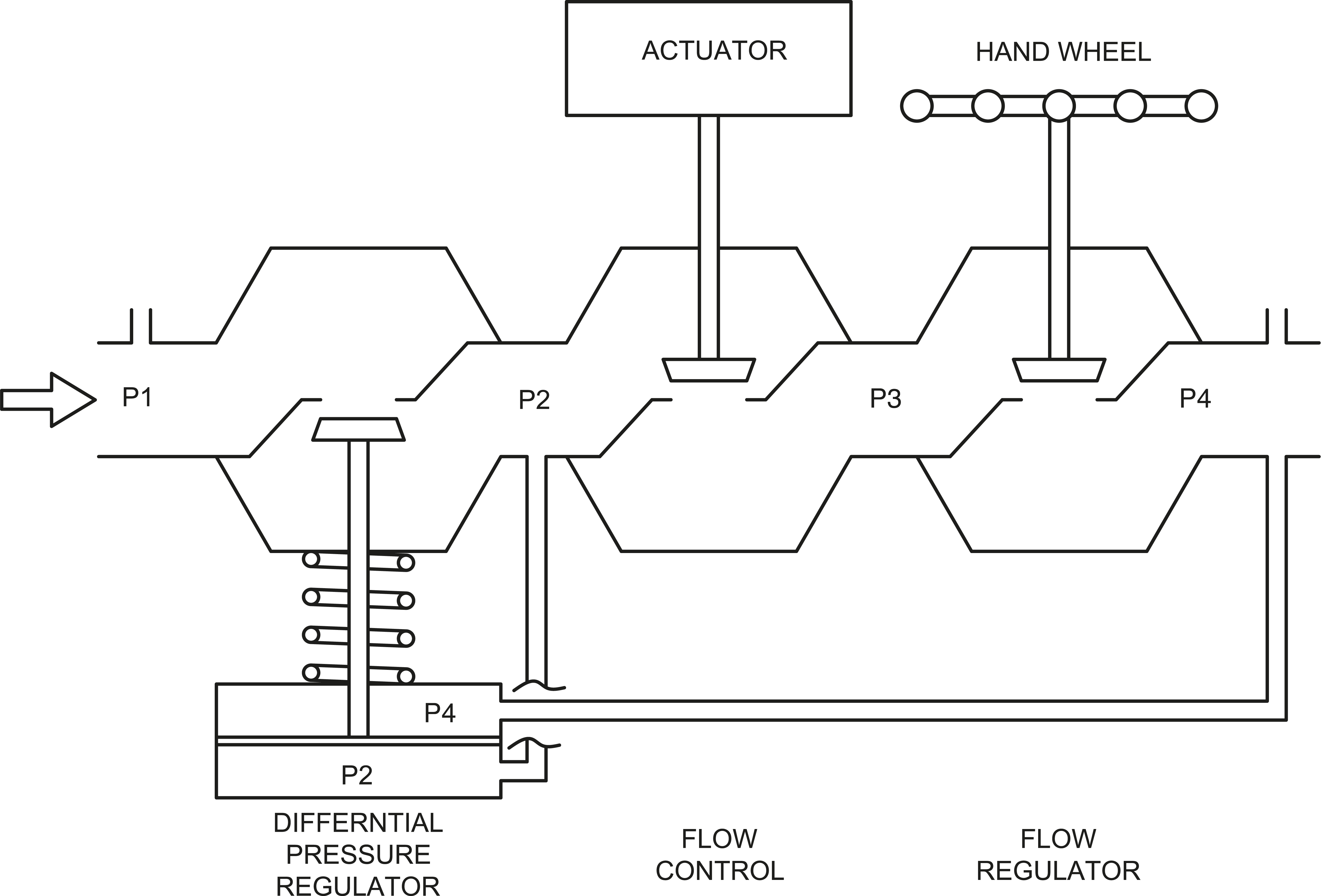
Figure 1a. Three-section IPCP.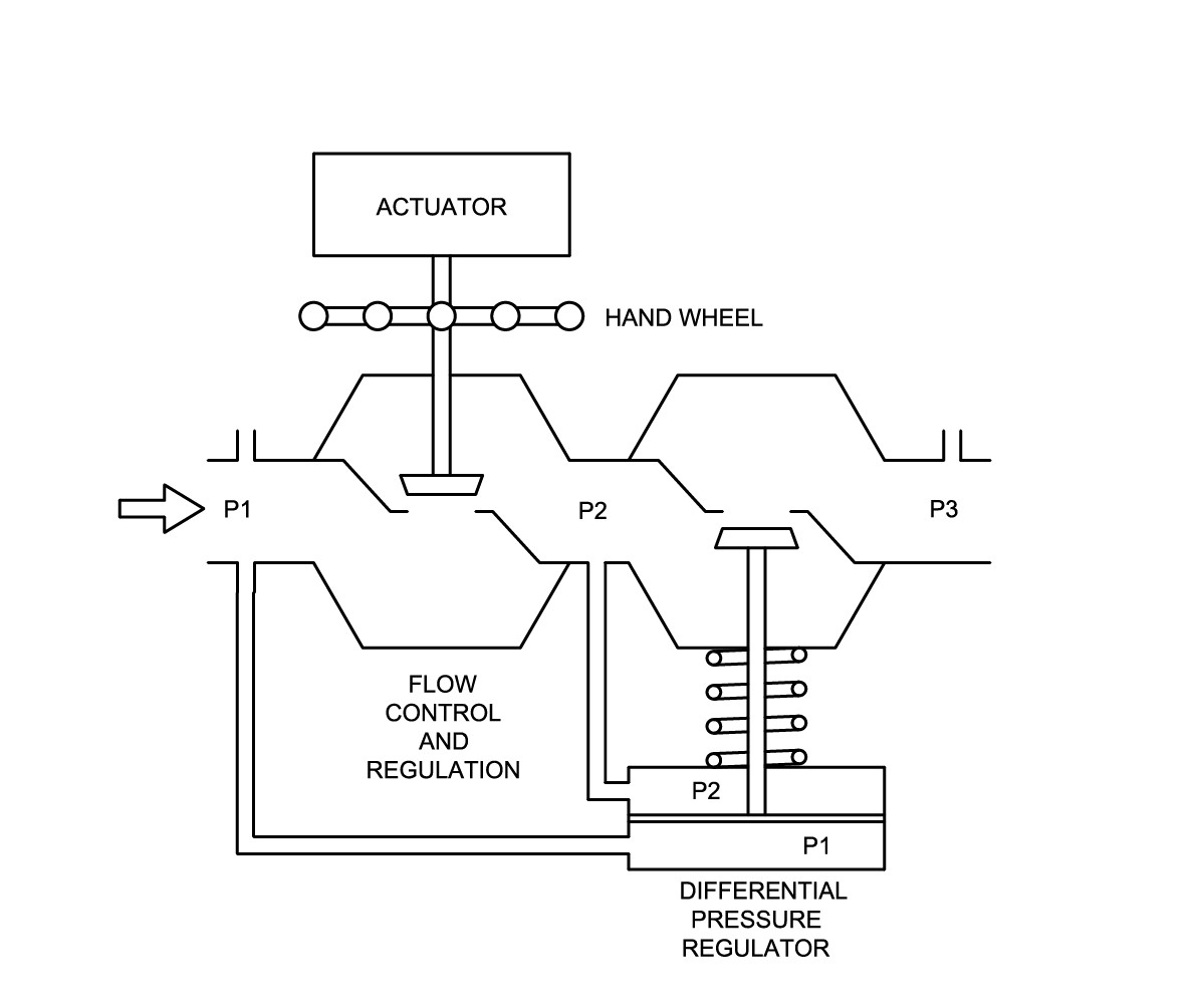
Figure 1b. Two-section LCCP
Some valves, as shown in Figure 1a, are made up of three distinct sections that correspond to the different functions of the valve, i.e., pressure regulation, flow adjustment, and modulating flow control. There is also the option for the flow adjustment and flow control functions to be combined within the same valve section as shown in Figure 1b.
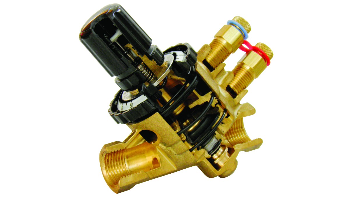
Each section of the valve works as follows: the inlet to the valve houses the differential pressure regulator. It features a flexible rubber diaphragm that flexes against a spring that simultaneously varies the size of the opening for the passage of flow. One side of the diaphragm is in contact with water from the inlet to the valve at a pressure P1, while the other side is in contact with water from the outlet to the valve at a pressure P4.
This means that if there is any change in the differential pressure in a range from P1 to P4, the position of the differential pressure regulator will also change. The result will be that the differential pressure P2 to P4 (i.e., downstream of the differential pressure regulator at the valve outlet) will always remain constant regardless of changes in the overall differential pressure P1 to P4. Hence the term "pressure-independent": no matter how much external pressures vary, the performance and function of the valve will not be affected as long as it is within its working range. In the center section, there is a control valve to achieve the required design flow value, as specified by the manufacturer.
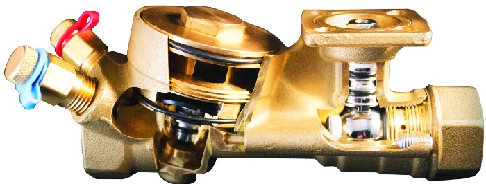
The required flow rate can be set using the flow setting dial built into the valve body. The stroke of the control valve is not affected by the flow adjustment. A full stroke provides good flow control, especially when using a modulation actuator. The control characteristic of a PICCV is not affected. If the flow adjustment device is combined with the modulation control valve (Figure 1b), as the flow setting is adjusted, part of the control valve travel is used to regulate the flow.
The reduction in stroke affects modulation flow control through the remaining valve travel, once configured. Therefore, the control valve stroke available for modulation is limited. This limitation in modulation could affect the performance of the valve and end up converting the valve to an ON-OFF type.
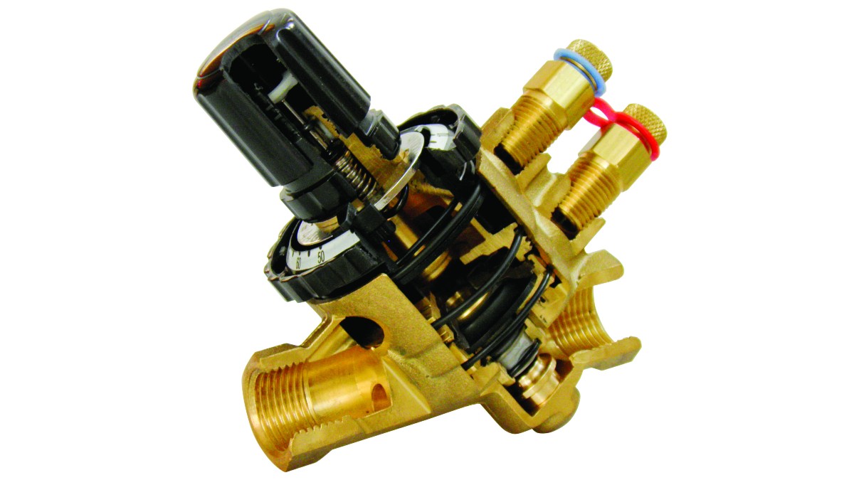
Pressure taps built into the valve allow the overall pressure differential P1 to P4 (or P3) to be measured to ensure that the valve is operating within the differential pressure range set by the manufacturer. Careful evaluation will be necessary whenever static balancing (DRV and commissioning sets) and IPCP (dynamic balancing) are desired in the same system. A system where the terminal units are equipped with static balancing without dynamic protection will only have a full design flow during commissioning and the flow will change under load conditions.
At the outlet to the valve body there is a flow adjustment device. This allows the valve to be set to partial. This can lead to excess flow through the DRV and reduced system pressure, which would result in an impact on the performance of the PICV (low start-up). In other words, there will be an effect on the overall performance of the system.
The performance of PICVs makes them ideal for use in variable flow systems.
Any changes in P1 pressure (such as those that could be caused by changes in pump speed or by valve shut-off in other parts of the system) will be automatically compensated for by the action of the differential pressure regulator. The controller will simply increase the resistance of the valve if P1 increases or decrease it if P1 decreases.
In addition, the regulator's ability to maintain a constant pressure differential between P2 and P3 has two important implications. First, with the control valve fully open and the flow adjustment device set to its required value, the valve effectively becomes a constant flow regulator (since a constant pressure differential through a constant resistor will result in a constant flow rate).
Therefore, if installed without the actuator, the valve can be used as a flow limiting valve, to keep the flow at a fixed preset value, regardless of changes in other parts of the system. This can be useful in by-pass circuits.
Second, by maintaining a constant pressure differential across the control valve and flow adjustment device, the authority of the control valve is maximized. The authority of a valve is an indication of how accurately the valve will be able to modulate flow when opened and closed. To achieve a correct level of authority, the pressure differential across the valve must be at least 50% of the total pressure differential in the pipe, branch, or circuit for which you are controlling the flow.
Such a valve would be considered to have an authority of 0.5. It is often impossible to size conventional 2-way control valves with such a high level of authority, because the controlled circuit can include the terminal unit and pipe losses to a remote pump or DPCV. In many applications, this condition requires 2-way valves with too high resistances. In this way, the most common authority value of valves is usually 0.2, which is a figure that is far from ideal.
In a PICV, the level of authority is improved because the differential pressure P2 to P3 (or P1 to P2) through the control valve and the flow adjustment device is effectively the circuit by which the valve controls the flow. This means that there is no need to take into account the pressure loss of the terminal unit and piping for valve selection, and valves can be selected based on flow rate only.















Así es, Armando. Gracias por leer el artículo.
Saludos.