
 One of the main challenges of every refrigeration system designer is, without a doubt, the selection of the pipe for a correct performance of the system.
by Alonso Amor*
To perform this task one of the parameters that must be considered is the loss of load generated along the entire refrigeration circuit. Pressure loss (or pressure drop) is the pressure differential measured at two different points in the system.
There are points where a pressure drop is necessary as is the case of the expansion valve, however, a pressure differential in other components is not desirable because these losses will cause an inefficient performance of the system generating a greater energy consumption for the end user.
Pressure drops are totally inevitable, since every fluid moving within a delimited volume will have a pressure differential caused by the resistance of the medium represented by friction, being that, the longer the length of the pipe, the greater this differential. The rule is simple, a higher speed implies a greater loss and a smaller diameter greater speed.
If we strictly apply the previous statement, the pipe with a larger diameter will always be the best, since this way we will have lower speeds and lower losses, causing a greater efficiency. But when we begin to think from a practical point of view, the larger the diameter, the greater the demand for refrigerant fluid and with this we reach new problems since an excessive load is always a complication for the control of liquid, in addition, from the perspective of the end user, the use of larger diameters will always be a greater investment and this can make the installation unfeasible.
It should be borne in mind that inside a pipe it is not only refrigerant that is circulating, there is also a portion of oil that in combination with the refrigerant must return safely to the compressor. To achieve this we must guarantee sufficiently high speeds that promote a correct drag of the oil, being that, high speeds will bring as a consequence greater pressure drops.
Due to the complexity of the problem, there is no exact equation or method that results in the pipe diameter that must be used in each of the segments of the circuit, which is why the designer must know the principles of selection and apply them correctly always looking for an adequate functioning of the system.
Suction line
The suction line is the segment of the cycle where the correct selection of the pipe is most critical since any pressure drop in this stretch will generate a higher compression ratio directly affecting the efficiency of the system. The selection of this line should be based on the pressure drop equivalent to 1.1 °K taking as a reference the evaporation temperature of the system (see table 1).
The pipe must follow the most direct path possible avoiding the installation of unnecessary curves that can generate an additional loss of pressure. In the same way, all those components that are not totally necessary for the operation of the application, such as pressure regulating valves or unspecified filters, should be avoided.
Table 1: Pressure drop equivalent to 1.1 K at different evaporation temperatures
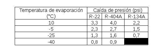
The suction line is also the point where the designer must be more careful with the relationship between pressure drop and fluid velocity since the refrigerant in a gaseous state has a low density making it difficult to drag oil. Typical speeds for the sizing of the suction line range from 5 to 10 m / s, being that in ascending stretches the speed should never be less than 7.5 m / s.
In systems where the suction line is very long, there will be situations in which it will be necessary to make a decision between maintaining little pressure drop with low speeds, or increasing the speed (with greater losses) looking for a better drag of the oil. In these situations, the pipe that offers an adequate speed should always be selected, even if the efficiency is punished, since it will always be better to have a slightly less efficient system with a correct return of oil than a system with low pressure drop without lubrication or problems in heat transfer.
Download line
In commercial refrigeration it is often not necessary for the designer to perform a load loss calculation on the discharge line since this line is sized by the manufacturer within the condensing unit assembly. In addition, in these coupled systems the length of the line is not considerable so the loss of pressure or oil drag will not be a problem.
However, there are systems with remote capacitor where it is necessary to perform a pressure drop analysis. As a rule, the pipe of these systems should be sized for a pressure loss no greater than 5 psi. Typical download line selection speeds range from 10 to 13 m/s. Special attention should be taken to never select diameters that generate speeds greater than 15 m / s since at this point the line may begin to present excessive vibration and high noise levels.
Liquid line
In contrast to the other lines, the liquid line is a segment of the cooling system that does not (or should not) transport refrigerant in a gaseous state. For this reason, the speed of the fluid is not a primary factor for the proper functioning of the installation since the oil is completely mixed with the liquid coolant.
The function of the liquid line is to supply the expansion valve with a constant flow of sub-cooled refrigerant. To perform this task, it is necessary that during the passage of the fluid in the pipe there is no saturation condition resulting from pressure drops. Refrigerant saturation in the liquid line will result in poor system performance as a sequence of poor expansion valve operation.
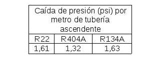
Commonly the horizontal stretches of the pipe are not a problem in terms of pressure drop, on the contrary, the ascending segments need special attention. High load losses in ascending segments are inevitable, Table 2 shows the pressure drop per meter of upwelling pipe. To avoid poor system performance, it must be ensured that the sub-cooling in the liquid line is sufficient so that even with pressure loss, the fluid does not suffer saturation.
Table 2: Pressure drop per meter of uppipe for different refrigerants
The sub-cooling of each system is variable depending on each application, air-cooled condensers commonly offer a sub-cooling of 3 to 6 °K. If due to a high pressure drop the system needs additional sub-cooling, another auxiliary sub-cooling method must be coupled. Table 3 shows the saturation pressure change for each degree of sub-cooling.
Table 3: Saturation pressure change for each degree of sub-cooling for different refrigerants based on a liquid temperature of 40°C
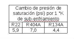
For example, a 7-meter upwelling liquid pipe using R404A will have a pressure drop of 9.24 psi (see table 2), if the condenser gives a sub-cooling of 3 °K the system withstands 21 psi of pressure drop without generating a saturation condition (see table 3). In this case no additional sub-cooling method will be necessary.
Other factors such as dirty filters, excess service valves or solenoid valves should be avoided so as not to generate an excessive pressure drop, which will bring saturation of the fluid also known as "flash gas".
In terms of coolant velocity, it should only be verified that the liquid line is projected with values below 1.5 m/s to avoid the phenomenon known as water hammer, which can occur after the operation of solenoid valves.
General recommendations
For the correct functioning of the system, the following factors must be considered in the selection of the pipe.
- Always use L or K type copper pipe
- Never select the diameters of the lines based on the connections of the condenser or evaporator unit
- If selection tables are used, verify that the conditions of calculation of the same are in accordance with the system that is being projected
- Always search for the pipeline to have the most direct path possible
- Avoid the use of unnecessary accessories
*Alonso Amor – application engineering coordinator at Heatcraft Brazil.


Para una unidad condensadora de 20 HP evaporando a -5ºC con 41,5 Kw R404A qué margen de potencia debemos tener en cuenta para una longitud de tubería entre evaporador y unidad condensadora de 25/30 mts ?
Aparte claro de tener en cuenta suficiente carga de refrigerante y controlar nivel de aceite. El equipo incorporará separador de líquido, separador de aceite, bypass de arranque (con válvula de retención) y presostatos de seguridad.
Muchas gracias