
 The implementation of this class of valves encourages energy savings in variable volume air conditioning systems. by Julio Londoño*
Decoupled or variable volume ice water air conditioning systems that use two-way valves have become the norm today. The reason is that these offer significant savings when compared to constant volume systems that use three-way valves. The savings are obtained thanks to the fact that the speed of the water distribution pump, or secondary circuit pump, is reduced to maintain the supply of ice water only to the equipment that requires it, in this way the pumps and coolers are operated according to the load requirements of the building and not 100% as in the case of constant volume systems. By reducing the speed of the pump, a fairly large energy saving is obtained thanks to the affinity laws of these. According to the law of affinity, energy consumption changes at the rate of the velocity cube. This means that a 10% change in speed represents a 33% change in energy consumption. The use of variable frequency drives (VFDs) has become standard in HVAC systems, especially in water distribution. Today these devices are low cost and high reliability with a fairly high Cost/Benefit ratio. Another area where savings are made is in the cooling plant. By varying the flow of water the control of the cooling plant adds or subtracts chillers to match the cooling capacity to the actual load of the building. Figure 1 - Typical diagram of a decoupled hydraulic system, also called variable volume.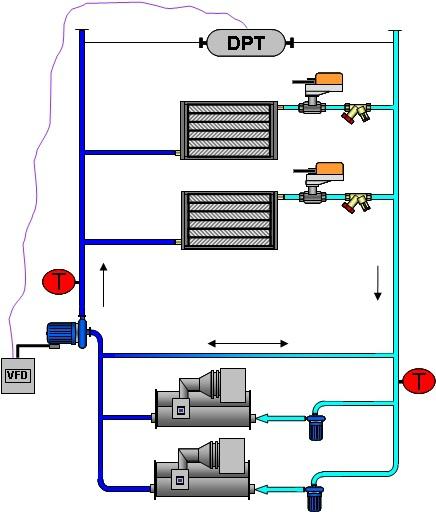 In a decoupled hydraulic system the production of ice water is decoupled from the distribution by a bypass. In the primary circuit constant volume pumps are used. The water in the secondary circuit is variable flow and the pump speed is controlled with a Differential Pressure Transducer (DPT) sensor. Two-way control valves with balancing valves are used in cooling coils. While the benefits, from the energy-saving point of view of a decoupled system are quite large; these systems also offer new challenges for the designer and the building operator. Many analyses have been made of water-ice plants, especially in the wake of the push for green buildings and LEED certification that require building performance to be measured and compared to energy consumption values modeled during design. Performance factors
It has been found that many do not perform according to the calculation parameters and the savings obtained are not as expected. There are many factors that influence this low performance, in this article we will discuss some of them, especially those related to the control of ice water in the building. When you have an automation system in the building that manages the ice water plant, the main goal is to maintain control and save energy. The cooling plant control algorithm must maintain the ice water set point and also operate as few coolers as possible by letting them work in the high operating ranges. Chillers are expected to work in their high capacity ranges because most cooling equipment, especially screw and centrifuge equipment, has its highest efficiency range when operating at high loads. Operating fewer chillers has an additional benefit as fewer pumps are operated at once. That is why it is more efficient, from the point of view of the cooling plant, to have a chiller working at 90% of its capacity than two working at 45%.
The control algorithm must add and subtract chillers according to the load conditions of the building. As the control valves open due to the increased load, then the flow in the secondary circuit increases, thus exceeding the maximum flow of the evaporator and forcing water through the bypass. When you have enough flow in the bypass to add another cooler then this is added to the sequence to compensate for the overflow. In addition, having overflow in the bypass line loses control over the ice water set point, as the water that returns hot mixes with the cold water generated in the primary circuit. Figure 2 - Over flow in the secondary 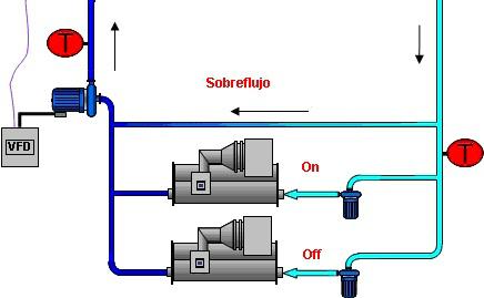 circuit The next cooler is added to the sequence only when the overflow in the bypass is equal to or greater than the nominal flow of the cooler to be added. A chiller is only subtracted from the sequence if when removed the remaining flow does not exceed the maximum total capacity of the coolers that are enabled, always observing that the ice water temperature is at the set point. To make the decision to add or subtract a cooler from the sequence; the ice water plant control algorithm can use water flow and direction sensors in the bypass or temperature sensors, one in the return in the primary circuit and one in the supply in the secondary circuit. But it may happen that despite having all the coolers enabled you still have overflow in the bypass. This causes the water set point not to be reached, so the coolers are not removed from the sequence. At this time the cooling plant control adds chillers to the sequence, not to meet the cooling needs of the building, but to maintain the pumping needs of the system. This overflow originates in the coils of the air handlers and in addition to the additional pumping surcharge it also has the consequence that it affects the heat exchange, in such a way that the water temperature returns cold to the plant. This causes active coolers to operate at partial loads to reach the ice water set point. A clear symptom of poor performance of the ice water plant is when you have several chillers working simultaneously at very low load. When really the need for cooling the building can be satisfied using a smaller number of chillers working at high loads. Low Water Delta T Syndrome
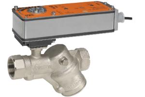
If the Delta T is low then the flow must be increased to maintain the load of the cooling plant, this causes the total efficiency of the cooling plant to drop considerably. This phenomenon is called Low Water Delta T Syndrome. Two types of waste are then presented, the first is when using more energy in the pump due to the overflow expense. The second occurs by not using the nominal capacity of the coolers due to a low Delta T, this is the larger of the two. There are many documents that explain and offer solutions to the problem of Low Delta T Syndrome, and there are also many factors that can contribute, but when you have a good installation with a well-designed and sized system and still this problem arises; the most likely cause is in the control valves and in the balancing of the system. Inadequate balancing and/or control valves operating inefficiently generate such an overflow in the system sufficient to make the plant operate far from the optimal point incurring very high operating costs. In the following sections we will see what factors generate overflow and how it affects heat transfer, we will also see what options we have to avoid this phenomenon. The use of pressure-dependent valves is widespread, such as the Balloon type or the ball valves with a characterized disc. These are called pressure dependent because the flow through them, for a given position of the valve, depends directly on its differential pressure. The higher the pressure, the greater the flow and vice versa. Control depends on how thin the valve can control the flow. Fine control occurs when the zone temperature controller varies the position of the valve to react to a load change and this movement corresponds exactly to the flow change required to return the zone temperature to its set point. A control valve will have fine control when it is operating under the design conditions for which it was selected. Likewise, an oversized valve, at the slightest movement of the actuator, will let more water pass through than required, thus cooling the area, when this happens the controller reacts in the opposite way to counteract the overcooling. This behavior is typical of oversized valves. Oversizing in the control valves causes the controller to constantly fluctuate (Hunting) and have difficulty maintaining the temperature set point. Thanks to this, the selection of control valves is critical for the proper functioning of the ice water plant. The principle of selection of the control valve recommends that this be the element with the greatest fall in the branch, thus ensuring good control. Selection is made assuming a given pressure drop, normally assuming a pressure drop of 4 psi. This is a legacy that is incorrectly applied today. Originally coils were designed with a pressure drop of 4 psi, and the principle for valve selection stated that the valve should have at least the same coil pressure drop, so it was assumed that the coil would have the highest pressure drop of the branch. Today coils have much smaller drops, but control valves are still selected with the same criteria. In addition, a balancing valve must be added because the valves closest to the pump are subject to a higher pressure. The balancing valves ensure that no more flow is supplied than required, normally it is the balancing valves that have the highest pressure drop in the branch. The ideal would be to select the control valve by doing a pressure drop analysis on each branch after doing the balancing, but this in practice is impossible. For selection, the valve flow coefficient equation or Cv is used:
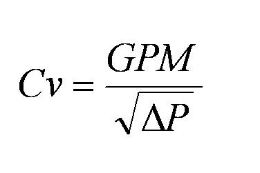
1 Cv = 1 gallon of water at 60 DegF passing through a fully open valve with a pressure drop of 1 psi. Let's take an example, if we have a coil of 100 GPM, and assuming a drop of 4 psi, then, according to the equation, we need a valve with a Cv of 50. The design flow can only be obtained when the valve is fully open and you have a pressure drop of 4 psi through it. This is the criterion by which all control valves are normally selected. But the operating conditions are regularly a far cry from the design conditions. Normally working at partial loads and with variable pressures. Suppose on a cold day where the controller requires only 20% of the cooling capacity. For our example this corresponds to 20 GPM, when doing the calculation of Cv, assuming that the pressure does not change then the required Cv is 10, then the selected valve (Cv = 50) becomes oversized and the control becomes very poor at partial loads. Note: in the second part of this article we will see the topic of differential pressure of valves, balanced hydraulic systems, among others. * Julio Londoño is the Product Manager of Belimo ([email protected])


Leave your comment