 It is essential to recognize the differences that exist between the different compression equipment, part of which depends on the proper functioning of any system that uses it, especially when it comes to industrial refrigeration.
by Germán Robledo*
It is essential to recognize the differences that exist between the different compression equipment, part of which depends on the proper functioning of any system that uses it, especially when it comes to industrial refrigeration.
by Germán Robledo*
This is the first article in a series in which I will address the topic of screw compressors. Here I will open a space to compare this equipment with other varieties on the market, for example reciprocal compressors and twin-screw compressors.
With this I want to provide basic information about the theory and operation of screw compressors, analyze the compression process and offer a comparison between the equipment offered by the industry today, as there are many differences between them.
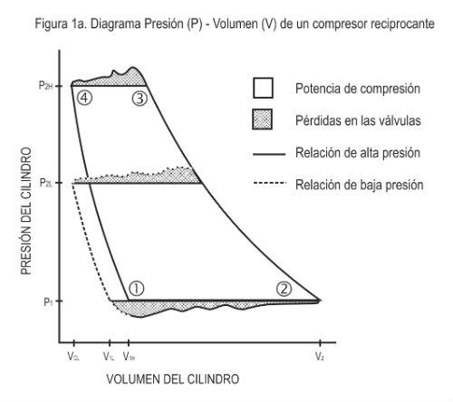
An excellent help in understanding why different compressors work in a certain way is the P-V diagram that represents the pressure and volume inside the cylinder of a reciprocating compressor or the propeller in the case of a screw compressor.
The area enclosed by the P-V diagram represents the work required for compression following the expression W= ∫Pdv. Mechanical and friction losses are not taken into account in the diagram, only compression and flow losses. The points listed in the diagram are:
1.beginning of suction
2.end of suction, beginning of compression
3.end of compression, start of download
4.end of download
 Basic differences
An important difference between screw and reciprocating equipment is that the latter use suction and discharge valves for each cylinder. They function as one-way check valves. The suction valve allows the flow of gas into the cylinder during the intake stroke, while the discharge valve allows the compressed gas to exit the cylinder during the discharge stroke.
The valves are opened by the pressure of the gas that introduces a pressure drop along the valve. The gas pressure must exceed the force of the valve spring, a force that is due to the area of the differential valve plate and flow losses.
This pressure drop is shown in the P-V diagram (Figure 1a) as an area above the discharge pressure for the discharge valve and the pressure area below the suction for the suction valve. These areas represent the power losses associated with valve operation. In addition to generating a loss of power, valves are components that require a lot of maintenance.
Screw compressors do not have valves, instead, they have ports. Let's look at one propeller in particular. In a twin-screw compressor, a propeller is the volume enclosed between a slot in each rotor and the outer shell. During admission, the propeller is exposed to suction and filled with gas. When the maximum volume of the propeller has been reached, the rotor rotates beyond the port opening and the gas is trapped in the propeller.
As the rotors continue to rotate, the volume of the propeller decreases and compression occurs. After a certain amount of compression, the propeller opens to the discharge port and the additional rotation reduces the volume to zero, expelling the gas from the rotors.
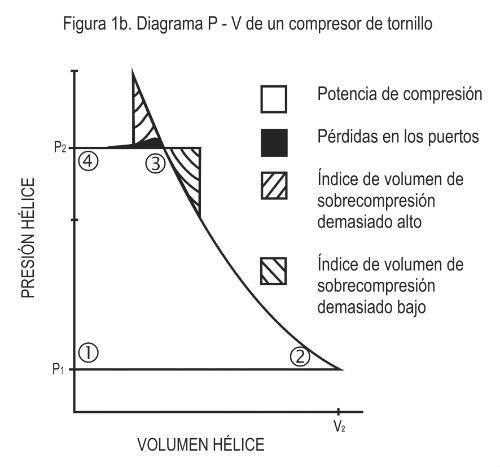 As seen in the P-V diagram (Figure 1b), the flow losses associated with the suction port are negligible. A small loss of energy occurs during discharge when the discharge port begins to open and the flow area is small.
The size and position of the discharge port determine the compressor's built-in volume ratio (volume index). The actual definition of integrated volume ratio is the maximum volume of the propeller in the suction (swept volume) divided by the volume of the propeller when the propeller is opened to the discharge port.
The volume ratio is related to the compression ratio by the thermodynamic expression:
P2/P1 = (V1,/V2)k
where:
P2 = discharge pressure, psia (absolute pressure)
As seen in the P-V diagram (Figure 1b), the flow losses associated with the suction port are negligible. A small loss of energy occurs during discharge when the discharge port begins to open and the flow area is small.
The size and position of the discharge port determine the compressor's built-in volume ratio (volume index). The actual definition of integrated volume ratio is the maximum volume of the propeller in the suction (swept volume) divided by the volume of the propeller when the propeller is opened to the discharge port.
The volume ratio is related to the compression ratio by the thermodynamic expression:
P2/P1 = (V1,/V2)k
where:
P2 = discharge pressure, psia (absolute pressure)
P1 = intake pressure, psia (absolute pressure)
V2 = discharge volume, feet3/min. or feet3/rev.
V1 = intake volume, feet3/min. or feet3/rev.
k = isentropic exponent (1.28 for NH3)
About the integrated volume ratio
For a screw compressor to operate at maximum efficiency, the integrated volume ratio must be matched to the system pressures by the above equation.
If the volume ratio is too high (small discharge port), overcompression occurs, i.e. the propeller pressure increases above the discharge pressure before the propeller opens to the discharge port.
If the volume ratio is too low (large discharge port), undercompression occurs, i.e. the propeller opens to the discharge port before the discharge pressure is reached. This results in gas receding to the propeller, immediately pressurizing the propeller to the discharge pressure. As shown in the P-V diagram (Figure 1b), the envelope or subcompression adds area to the diagram, thus adding energy losses.
Energy losses incurred by operation away from the optimal integrated volume ratio are shown in Figure 2. Several observations can be made from this curve:
For each integrated volume ratio there is a compression ratio where no overage or undercompression losses occur.
The full range of pressure ratios from 3 to 10 can be covered with (3) integrated volume ratios, with a maximum requirement of 1 1/2% additional BHP (assuming pressure conditions are constant).
It should be noted that the curve is only valid for ammonia. The curves change slightly to the left for halocarbons that have lower values for the isentropic exponent.
The curve shows the effect of a compressor with variable volume quotient similar to those recently introduced to the market. It can be seen that unless the pressure conditions are substantially modified, the variable volume feature will be pressed manually to save more than 1% in overall energy costs.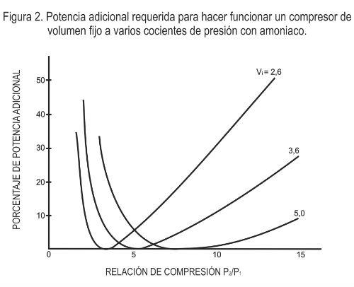
An example
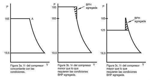
Consider a screw compressor in a cold storage application that requires an evaporator temperature of 5°F (19.6 psig) using ammonia. The system normally operates at 165 psig (90°F) of condensation. However, on hotter days, the condensing pressure rises to 185 psig (96°F). During the winter, the condensing pressure can drop to 125 psig (75°F). Assuming a volume index of 3.6, what are the losses associated with over- or undercompression in each condition?
Solution:
For the normal operating condition (165 psig condensation), the compression ratio is:
CP = 165 + 14.7 = 5.2
19.6 + 14.7
As shown in Figure 2, this is an ideal condition for a volume index of 3.6, as there are no losses due to over- or undercompression.
Figure 3a shows the P-V diagram for this condition.
 For the condition of 185 psig of condensation, the compression ratio is:
CP = 185 + 14.7 = 5.8
For the condition of 185 psig of condensation, the compression ratio is:
CP = 185 + 14.7 = 5.8
19.6 + 14.7
This condition requires more power, as shown by the additional area in the P-V diagram (Figure 3b). The striped area shows the additional power for premature opening of the discharge port (undercompression). Figure 2 shows that undercompression adds a little less than 1% power loss.
For the condition of 125 psig of condensation, the compression ratio is:
CP = 125 + 14.7 = 4.1
19.6 + 14.7
This condition requires less power, as shown by the smaller area in the P-V diagram (Figure 3c). However, there is a loss when functioning in this condition, represented by the striped area. A perfectly matching volume index will require less power than the volume index of 3.6. This loss due to overcompression rises to a loss of 2%, as shown in Figure 2.
Deadlock volume
Another basic difference between the reciprocating compressor and the screw compressor is the neutral volume of the reciprocating machine.
The neutral volume is necessary in a reciprocal machine to provide space for the valves and adjustment between the piston and the valve assembly. The neutral volume has a minimal effect on overall efficiency (BHP/tonne) because the compressed gas trapped in the adjustment space returns most of its energy to the piston by reexpansion. However, the neutral volume will reduce the volumetric efficiency (and therefore capacity) of the compressor.
With respect to the P-V diagram (Figure 1a), V2-V cL represents the swept displacement of the compressor and V1 is the volume of the reexpanded gas that was trapped in the adjustment space. The effective displacement of the machine is V2-V 1. It can also be seen that the loss of displacement worsens with high pressure ratios.
The screw compressor has no neutral volume but internal leaks that reduce its volumetric efficiency. Leaks are a result of operating adjustments between the two rotors and between the rotors and housings. Generally, however, the screw compressor suffers smaller capacity losses than the reciprocal, especially with higher pressure ratios.
There are oil-free and oil-injected screw compressor designs; most use the latter system. Oil-free compressors require synchronized gears to prevent the rotors from coming into contact with each other and with the oil seals between the bearings and rotors, making them more expensive.
Oil injection has the following advantages:
- Seal the operating settings.
- It provides lubrication for the rotors, avoiding contact between metals.
- It cools compressed gas and allows compressors to be used at higher pressure ratios than reciprocating and oil-free compressors. (The discharge temperature depends on the compression ratio.)
- Dampens compressor noise.
The addition of an oil separation system with oil injection is required, but it is a low price that must be paid for the advantages it provides. Even reciprocating compressor installations require oil separation. * German Robledo is a Mechanical Engineer. He has 15 years of experience in the industrial refrigeration industry, was manager of after market and services for the north of Latin America in the company York Refrigeration and is currently the sales director for Latin America of the company Vilter Manufacturing - Emerson Climate.