
 This is the second of six chapters that discuss technology in refrigeration compressors. In the previous edition we saw the topic of the compression process, now we will know the operation of a screw compressor.
by Germán Robledo*
This is the second of six chapters that discuss technology in refrigeration compressors. In the previous edition we saw the topic of the compression process, now we will know the operation of a screw compressor.
by Germán Robledo*
Visualizing how a twin-rotor screw compressor works is a bit more difficult than visualizing a reciprocating compressor. The helical grooves of the rotors and the unusual shapes of the ports complicate the picture.
Despite its apparent complexity, the screw compressor has relatively few moving parts: two rotors, bearings and a slide valve. Simplicity is one of the strong selling points of the screw compressor. This article will discuss the various components of the twin-screw compressor.
Rotors are the core of the screw compressor. A rotor has helical lobes and is called a male. The other rotor has helical coupling slots and is called a female. The most common rotor design is the 4+6 asymmetrical profile patented by SRM in Sweden. (See Figure 1.)
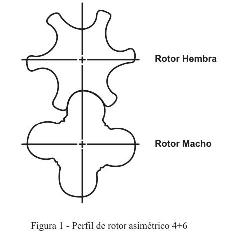 This profile has been proven to provide good efficiency and machinability. The asymmetrical design minimizes leakage paths through the rotor gear and provides a small "blow hole". The blow hole is the leakage area between the housing and the rotor tips in the gear. When in operation, the male rotor absorbs about 85% of the torque and the female about 15%. For this reason, in compressors flooded with oil, the male compressor drives directly to the female since one gear drives the other. In this way, only 15% of the input energy is transmitted through the rotor gear.
There is a pure bearing action between the rotors because they are driven in the step line. Therefore, when they are manufactured correctly, there is no sliding contact between the rotors and this serves to minimize wear.
In order to transport the loads generated by the gas pressures, both radial and thrust bearings must be used. (See fig. 2.) In a twin-rotor screw compressor, the bearing loads are quite high, and as a result, bearing failure is the main cause of compressor failure.
This profile has been proven to provide good efficiency and machinability. The asymmetrical design minimizes leakage paths through the rotor gear and provides a small "blow hole". The blow hole is the leakage area between the housing and the rotor tips in the gear. When in operation, the male rotor absorbs about 85% of the torque and the female about 15%. For this reason, in compressors flooded with oil, the male compressor drives directly to the female since one gear drives the other. In this way, only 15% of the input energy is transmitted through the rotor gear.
There is a pure bearing action between the rotors because they are driven in the step line. Therefore, when they are manufactured correctly, there is no sliding contact between the rotors and this serves to minimize wear.
In order to transport the loads generated by the gas pressures, both radial and thrust bearings must be used. (See fig. 2.) In a twin-rotor screw compressor, the bearing loads are quite high, and as a result, bearing failure is the main cause of compressor failure.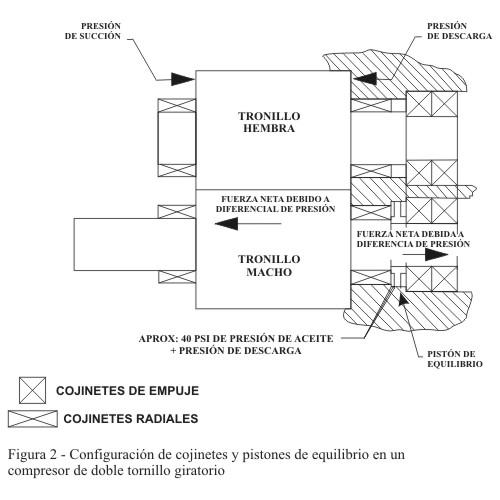
In most rotary twin-screw refrigeration compressors, radial loads are carried by sleeve bearings, these have several disadvantages. One is that they require boxes machined with a higher degree of accuracy (more expensive) than anti-friction bearings, because cuff bearings do not tolerate misalignments. Secondly, the sleeve bearings consume power due to the viscous drag of the oil.
On the plus side, however, the reliability trajectory of the sleeve bearings is excellent. As long as a good oil pressure is maintained and the system is relatively clean, the service life of the sleeve bearings is practically eternal.
The most common design of push bearings is an angular contact double ball bearing. Push bearings are the weak connection of the twin-screw compressor and the most common cause of compressor failure. The thrust charge is basically caused by the pressure difference from discharge to suction acting against the projected area of the rotor faces. The thrust load on the male rotor is greater than on the female rotor because the gas exerts force on the rotor gear.
For example, the thrust load of the male rotor on a 255 mm compressor running on ammonia under typical conditions is 4450 lbs. For this reason, a balancing piston is used on the shaft of the male rotor to help balance the thrust load. To be effective, the balance piston depends on the oil pressure behind it. In this way, the life of the thrust piston is very sensitive to the pressure of the equilibrium piston. Under normal operating conditions, female rotor thrust bearings have an acceptable life without a balancing piston. Even in a properly maintained system, push bearings are usually the parts that wear out first and, in some cases, should be considered maintenance components.
Capacity reduction in a rotating twin-screw refrigeration compressor is usually achieved with a slide valve. The valve is located in the stator box and forms a part of the rotor hole. (See fig. 3.) To discharge the compressor, the valve moves to the discharge end, which opens the compression area of the rotor again to suction. This provides a continuous, infinitely variable download method.
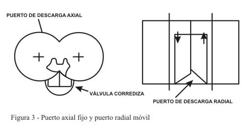 As shown in fig. 3, there is a radial discharge port on the slide valve and an axial port on the end face. In addition to the capacity reduction, the mobile radial discharge port will generally maintain the compressor's integrated volume ratio.
This is only effective until it drops to about 75% of the total capacity, depending on the design. After this point, the integrated volume ratio drops abruptly and causes the partial load efficiency to drop. The reason for this is that the radial discharge port no longer controls the point at which the discharge gas leaves the compression chamber. In comparison, the reciprocating compressor has an efficiency advantage over the screw compressor for part-load operation.
In a reciprocating compressor, discharge is usually achieved by keeping the suction valve plates open; this allows the gas to enter and exit the cylinder but does not allow compression to occur. Very little energy is consumed when running a cylinder under partial load. However, discharge must be achieved in steps, while capacity control in the screw compressor is continuous.
When designing a screw compressor, the operating speed should be considered. The reference used by the compressor designer is the peripheral speed of the male rotor measured in meters per second (m/sec.). The generally accepted peripheral speed range for oil-flooded compressors using SRM's 4+6 asymmetric profile is 30 to 60 m/sec. Operation at less than 30 m/sec. is uneconomical because the compressor is physically large compared to its capacity. Above 60 m/sec., efficiency and reliability drop sharply. With these speed considerations in mind, we can examine the various commonly used control configurations.
Control configurations
As shown in fig. 3, there is a radial discharge port on the slide valve and an axial port on the end face. In addition to the capacity reduction, the mobile radial discharge port will generally maintain the compressor's integrated volume ratio.
This is only effective until it drops to about 75% of the total capacity, depending on the design. After this point, the integrated volume ratio drops abruptly and causes the partial load efficiency to drop. The reason for this is that the radial discharge port no longer controls the point at which the discharge gas leaves the compression chamber. In comparison, the reciprocating compressor has an efficiency advantage over the screw compressor for part-load operation.
In a reciprocating compressor, discharge is usually achieved by keeping the suction valve plates open; this allows the gas to enter and exit the cylinder but does not allow compression to occur. Very little energy is consumed when running a cylinder under partial load. However, discharge must be achieved in steps, while capacity control in the screw compressor is continuous.
When designing a screw compressor, the operating speed should be considered. The reference used by the compressor designer is the peripheral speed of the male rotor measured in meters per second (m/sec.). The generally accepted peripheral speed range for oil-flooded compressors using SRM's 4+6 asymmetric profile is 30 to 60 m/sec. Operation at less than 30 m/sec. is uneconomical because the compressor is physically large compared to its capacity. Above 60 m/sec., efficiency and reliability drop sharply. With these speed considerations in mind, we can examine the various commonly used control configurations.
Control configurations
Large compressors from 163 mm to 321 mm (approximately 600 to 3400 ft3/min., respectively) are generally driven directly through the male rotor by a bipolar motor (3550 rpm). This translates into male rotor tip speeds of 30 m/sec for the 163 mm and 60 m/sec for the 321 mm.
In the case of compressors smaller than 163 mm, the speed must be increased to maintain an efficient and cost-effective speed at the tip. Two methods to achieve this are integral gear transmission and female rotor transmission.
Comprehensive transmission
In the integral gear drive approach, a set of gears is incorporated into the compressor design, which provides an increase in speed to achieve economical speed at the rotor tip. The added cost and complexity of an integral set of gears are justified by the following advantages.
a) It allows to handle different capacities by means of a single rotor size of the compressor.
b) It allows a physically small compressor to produce the same capacity as a larger and more expensive machine.
c) Allows greater flexibility when adjusting the size of the machines. An unusual capacity requires only one gear change.
d) Minimizes the inventory of tools and spare parts.
Female transmission
The focus with female rotor transmission provides a 50% increase in the peripheral speed of the male rotor compared to the transmission of the male rotor. This is due to the male/female speed ratio of 1.5 inherent in the 4 + 6 profile. However, because the male rotor absorbs 85% of the inlet torque, all this torque must be transmitted through the rotor gear. This requires hardening of the rotors along the pitch line to handle the additional driving forces. There is a greater risk of wear or damage to the rotor if such a transmission system is used.
Despite the low number of moving parts in the twin-screw compressor and its obvious simplicity, we cannot ignore some of the advantages of the reciprocating compressor. The screw compressor operates at speeds approximately three times higher than that of a reciprocating compressor and with high bearing loads that adversely affect the life of the compressor.
The reciprocating compressor is also more efficient in part-load operation. The various strengths and weaknesses of both reciprocating compressors and rotary screws ensure each a place in the market.
*  German Robledo is a Mechanical Engineer. He has 15 years of experience in the industrial refrigeration industry, was manager of after market and services for the north of Latin America in the company York Refrigeration and is currently the sales director for Latin America of the company Vilter Manufacturing - Emerson Climate.


Leave your comment